Your Cart is Empty


Process Vacuum System Applications & Oil-Free Technology
In this article, we dive into the differences between utility and process vacuum, measurement guidelines, and specifying vacuum systems to process applications for maximum system efficiency.
Written by: Bryan A. Jensen
Table of Contents
- Differences Between Process Vacuum & Utility Vacuum Applications
- Process Vacuum & Absolute Pressure Measurement
- Specifying Vacuum Systems to Process Applications
- Know Your Process: Batch vs. Continuous Processes
- Optimizing Production Efficiency
- Engineered System Solutions: Process Vacuum
“Double the vanilla. Double the salt.” …one of the tricks Grammy taught me.
I was standing on the dining room chair pulled in front of the kitchen window. Snow in the yard piled up above the sill and icicles dangling down to meet it with dark black evening beyond. I could just see up over the counter and into the bowl, where Grammy mixed the chocolate chip cookie batter with an electric mixer.
“Flour, baking soda, salt. Sift dry ingredients together. Combine the sugar and the wet ingredients in a separate bowl with cold butter.
Sure, you’ll need to put a little extra elbow grease into the beater. But cold butter is critically important to the final cookie. Nothing worth working for comes easy.”
The batter softens a little while mixing dry into wet. The last Tollhouse tweak is to put the oven-ready cookie dough balls out onto the frozen back deck for 9 minutes. When time's up, the now-chilled pan goes straight into the oven.
Backyard moose prefer carrots to cookie dough, so you’re safe leaving it out there for a short while. Dial up the temperature on the oven a few extra degrees and enjoy the soft-centered golden browned.

Key Takeaways
-
Distinct Nature of Process Vacuum: Unlike utility vacuum applications, process vacuum systems are integral to controlling the contents within vessels, pipelines, or chambers, necessitating precise management of internal conditions.
- Importance of Absolute Pressure Measurement: For process vacuum applications, measuring pressure on an absolute scale is crucial, as it provides a more accurate representation of the vacuum conditions, aiding in system design and performance evaluation.
- Complexity Due to Gas Composition: Process vacuum systems often handle diverse gas mixtures, including condensable vapors, requiring careful consideration of gas composition and its impact on system performance and material compatibility.
- Difference in System Installation: Process vacuum pumps are typically integrated within the core of production machinery, with hard-piped connections both upstream and downstream, contrasting with utility vacuum systems that often exhaust directly to the atmosphere.
- Tailored Solutions for Batch vs. Continuous Processes: Understanding whether a process is batch or continuous is essential for designing effective vacuum systems, as each type presents unique operational demands and challenges.
Differences Between Process Vacuum & Utility Vacuum Applications
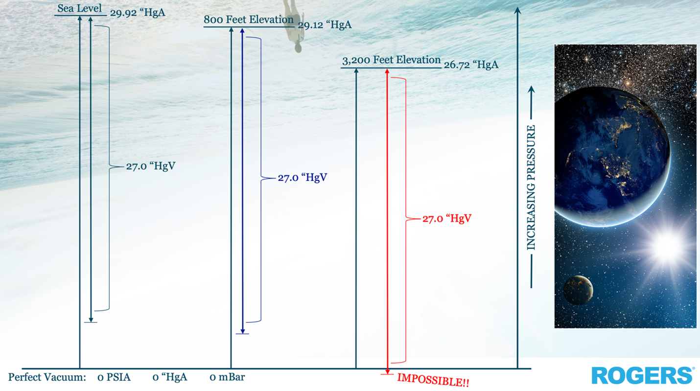
We covered ‘Utility’ applications late last quarter, and manufacturing’s other major category of industrial vacuum is ‘Process’. Utility applications use the difference in pressure between a vacuum system and the higher pressure of the atmosphere. This difference helps perform tasks in the physical world.
Utility applications are closely linked to the atmosphere and the air we breathe. This means they measure differential pressure (“HgV”) compared to the local atmospheric pressure (“HgA”).
Cost-effective oil-sealed compression technologies are most effective with inert gases. An example of an inert gas is nitrogen, which makes up 78% of the air.
A Process application, on the other hand, is all about controlling the contents of a vessel, pipeline, or chamber. What is the gas makeup inside the vessel? How much of it is in there? Process applications are all done to add value to ingredients, converting them into marketable products.
How do I most cost-effectively (and deliciously) turn this flour, salt, vanilla, and chocolate into a profit-maximizing cookie? Now, how do I make its process repeatable and efficient a million times over?
Process Vacuum & Absolute Pressure Measurement
Since "Process Vacuum" depends on its ingredients, we should always useAbsolute Pressure to measure. This helps us define the exact conditions inside theprocess.
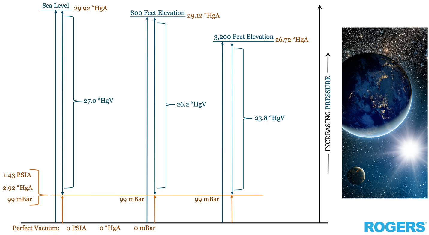
By using absolute conditions, we define how many gas molecules are in the vessel with the Ideal Gas Law. We also adjust our operating conditions to match the performance curve of the vacuum pump we choose.
This makes it easier to understand how vacuum pumps work in certain applications. When using an absolute pressure scale, you only need to know one thing: the operating pressure. This single variable is often enough to predict how well the vacuum pump will perform.
Specifying Vacuum Systems to Process Applications
Process Vacuum applications are much more complex than Utility Vacuum applications for several reasons. Two major differences include gas stream composition and vacuum pump control.
Defining Condensable Vapors
Process vacuum applications do not just compress air with a little bit of water humidity. Instead, they can pump a mixture of a huge variety of process gasses, inert or reactive. These mixtures often include condensable vapors.
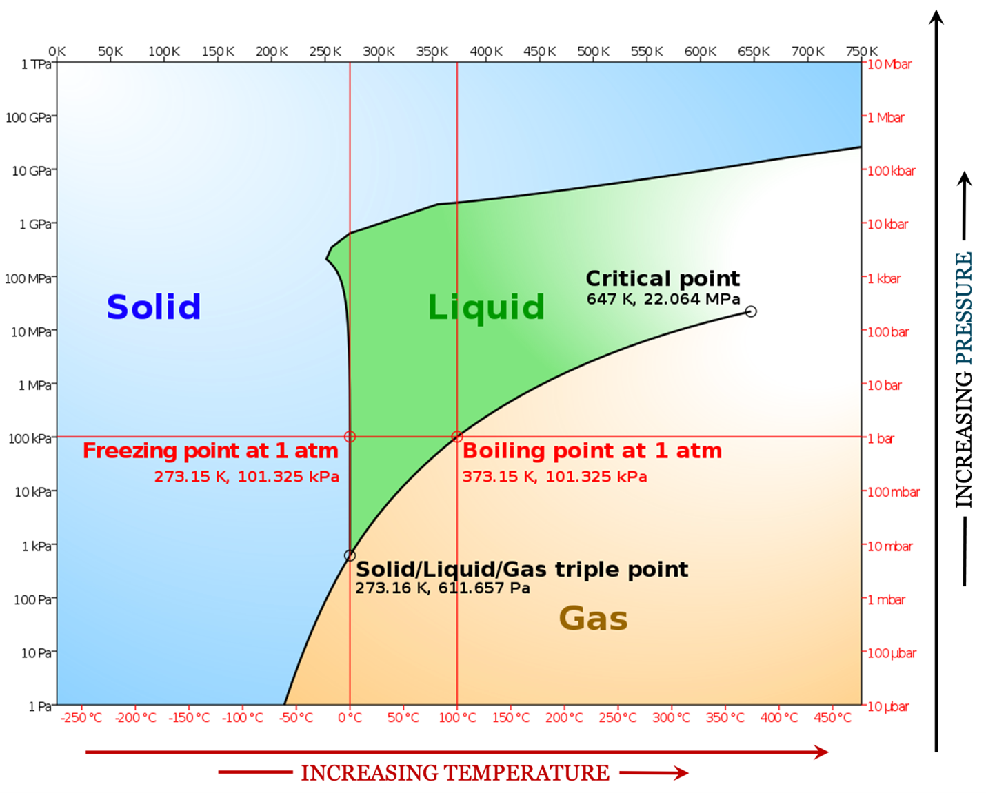
Condensable vapors are chemical compounds that are in the gas phase under vacuum, but liquid at atmospheric pressure and room temperature. In their liquid form, even harmless water (H2O) can be very chemically aggressive. This is true when it enters machinery.
Additionally, controlling these vacuum systems is a major consideration. Vacuum pump operation must be seamlessly integrated into the end user's process approach. This usually includes a plethora of proverbial flour sifters, eggbeaters, mixers, and ovens, autoclaves, reactors, or furnaces.
Vacuum System Installation: Location Matters
This brings us to another important difference to recognize between a utility and process vacuum system; how and where each is installed.
A Rogers KNW-Series rotary screw air compressor takes in air to power a factory’s air tools. In contrast, a utility vacuum pump has an open exhaust. This exhaust returns the air back to the environment. The air was taken in by the factory’s vacuum tools from hundreds of feet away.
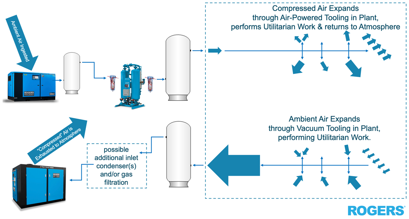
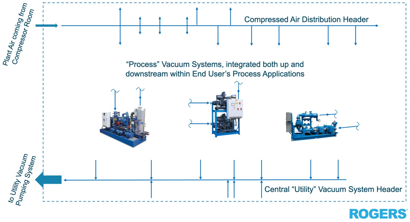
A process vacuum pump most likely has a hard-piped connection both up and downstream of the gas compression which occurs inside. Put another way, one can usually find a utility vacuum pump on the outside wall of any manufacturing facility. The exhausting air is pulled from the inside of the building, via the vacuum tooling, out into the atmosphere.
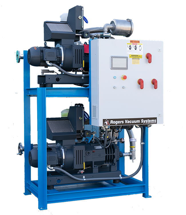
The Process Vacuum pump is likely installed underneath or embedded within the production machinery. Process action takes place both upstream ahead of the vacuum pump and downstream of its exhaust.
We can categorize "Process Vacuum" to help us size and apply vacuum systems. Let's cover the two main types of processes: Batch and Continuous.
Know Your Process: Batch vs Continuous Processes
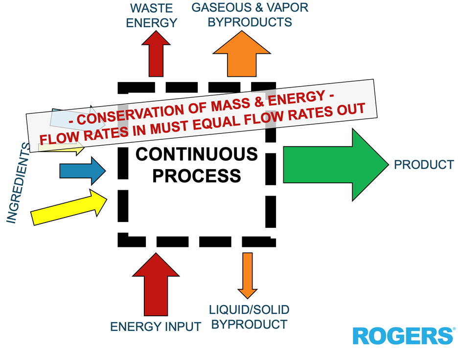
In a "Continuous Process," raw materials flow into a "black box process." This flow matches the output of refined products and byproducts. A few examples of continuous processes are:
- Column or reflux distillation of crude oil into various products such as diesel, kerosene, gasoline & lipstick
- Air separation of gasses such as argon, oxygen, nitrogen & helium
- The continuous vacuum forming & drying of PVC pipe, polyurethane door & window moldings or delicious krab nuggets.
As it is inferred in a Continuous Process, the “black box” system will be operating at reduced sub-atmospheric pressure (aka vacuum) continuously. Two types of loads exist when sizing and using a vacuum pumping system: condensable load and non-condensable load.
Condensable & Non-Condensable Loads
If the temperature and pressure are right, we can separate the condensable load. We should think about doing this if the chemical makeup allows it. This means we can remove the liquid load before the vacuum pumping system.
An inlet condenser or cold trap decreases the size of the vacuum pump while also improving reliability. The amount of liquid condensing in the vacuum pump or its exhaust system will be eliminated or reduced.
Sometimes fully eliminating the condensable load from the gas stream prior to the vacuum limit is impossible. Then, we must size the vacuum pump for the combination of the condensable load plus the non-condensable load. We must also ensure the condensable load remains in the vapor phase within the vacuum pump.
Applying Oil-Free Vacuum Technology for Process Applications
We can also supply and build a vacuum pumping system. This system will use materials that let the vacuum pump handle condensable liquids. It will also exhaust non-condensable gases as vapor into the user's exhaust system.
A number of tricks can help us accomplish any combination of the above, including:
- Directed exhaust temperature control
- Introduction of dry gas at various stages of compression
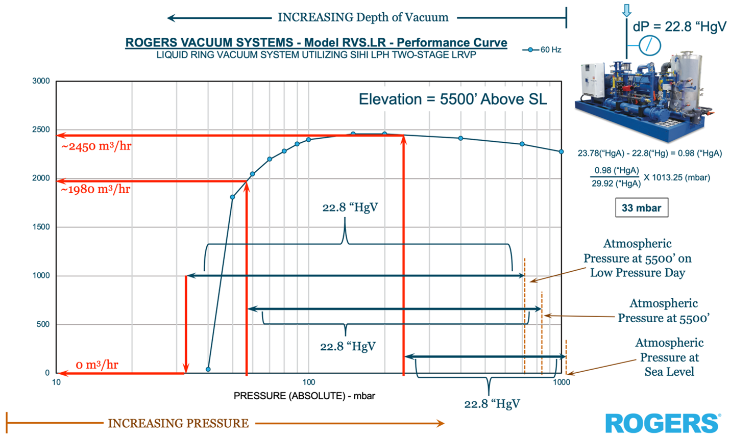
- Application of RVS.LR liquid-ring pumping technology
Batch Process: Evacuation Phase
A “Batch Process" requires starting & stopping the process, sampling & quality testing at stages along the way. Fill a vessel with the proper ratio of ingredients, heat them or cool them, shake them or stir them, react them or reduce them and move the resultant onto the next step. Clean the vessel out and start again a new batch.
Examples of batch processes include:
- Producing titanium sponge from a volatile liquid called "tickle" reduced through molten magensium
- Electronic water manufacturing beginning from silica sand
- Freeze drying Neapolitan ice cream for your next trip to the International Space Station

As with a Continuous Process, we must still consider both condensable and non-condensable loads of a Batch Process. This can be done by dropping out liquid or solid precipitate upstream, and sets up the vacuum pump for success, making sure it can safely handle the specific gas loads mentioned above.
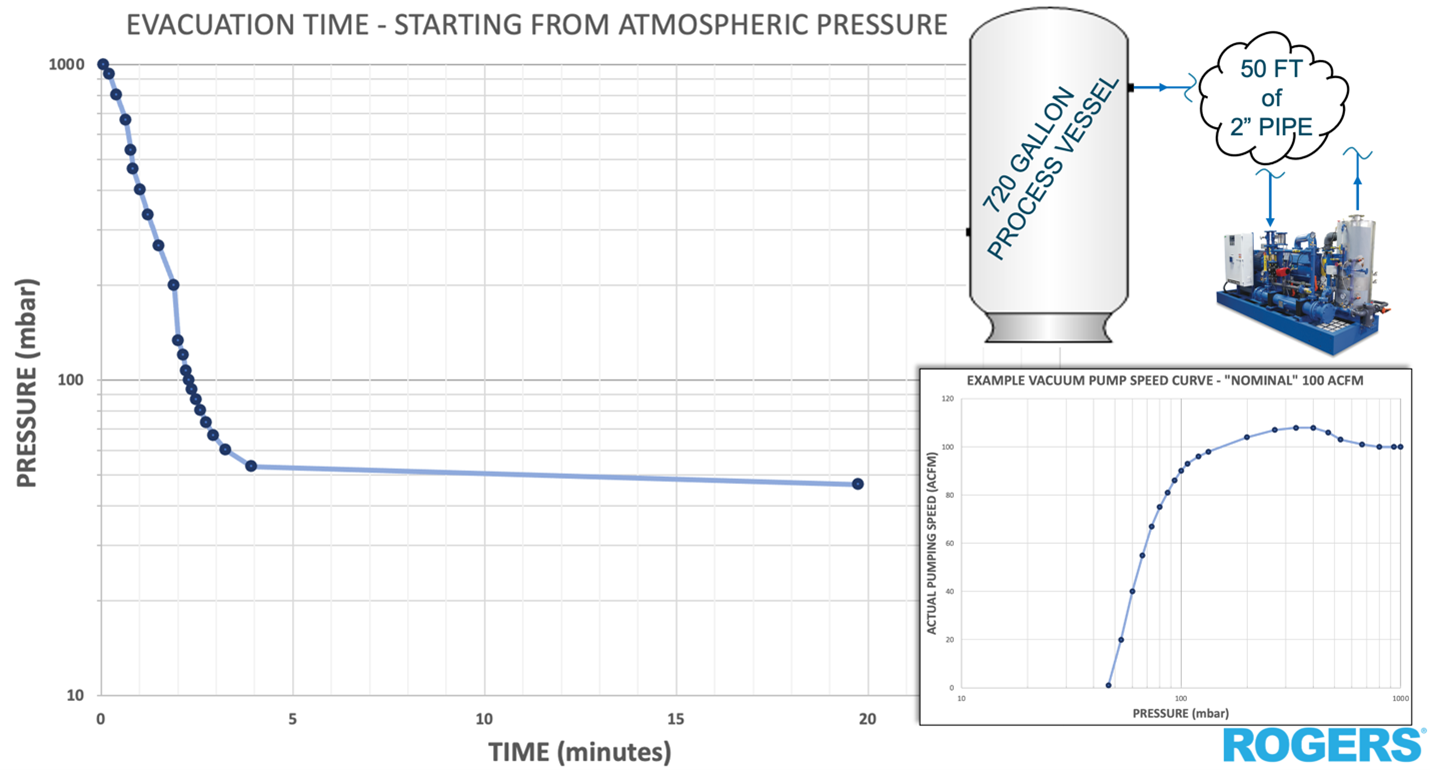
Any Batch Process that needs low gas pressure inside a vessel, pipeline, or container will have an extra step. This step happens when the container is exposed to the atmosphere or experiences pressure changes between batches. We call this step the “Evacuation” phase.
Optimizing Production Efficiency
We also must consider the end user’s batch cycle time. Cycle time relates to the physical size and volume of the vessel used to maximize the process's efficiency. These factors ultimately lead to maximizing client profitability.
Here's an example:
A batch of high-grade metal is reduced in a vacuum furnace. This process takes 54 hours under vacuum to complete. The time to evacuate the furnace takes 15 minutes.
The evacuation time only accounts for about half a percent of the overall batch production cycle. Because of this, we can likely only use one pumping system for both evacuation and holding phases.
Here's another example: say the batch requirements are a product with a much shorter cycle time. They want to the batch to remain under vacuum for 12 minutes. Imagine that evacuation time is 5 minutes.
Under these process assumptions, we need one of two things. We need either a bigger pumping system to evacuate faster, or more ovens to stagger batch cycles.
Applying Evacuation & Holding Pumps to Batch Processes
Taking the latter approach in the example is typically preferred. Using the existing pump to work on one oven while the others in the line are holding vacuum will lead to higher production volume without the high cost of new vacuum machinery.
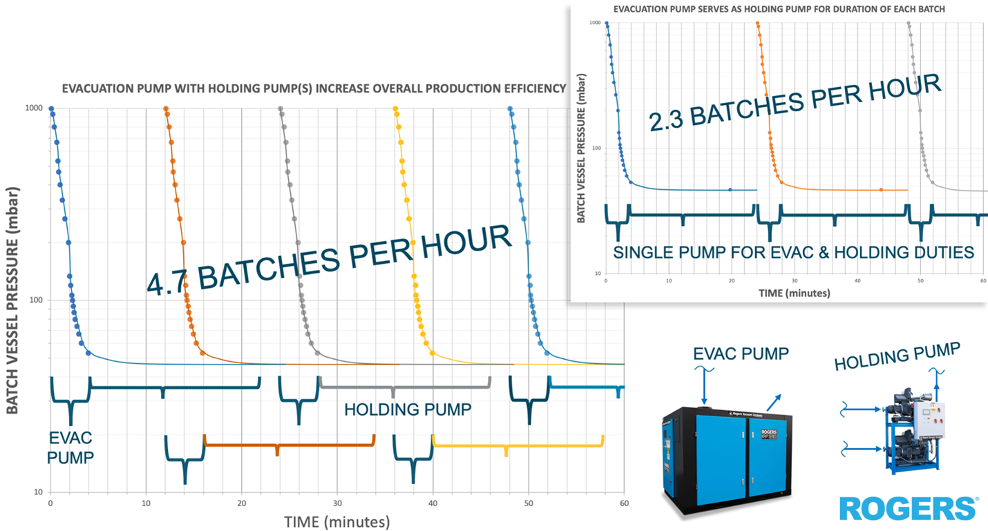
We’ve now created the familiar scenario where there is an “Evacuation Pump” performing the ‘hog-down’ of the process vessel. A secondary “Holding Pump” does the job of maintaining the low pressure setpoint required by the process for the duration of the batch cycle. The Evac Pump is sized for removing the bulk gas in the vessel. This reduces the pressure to some predetermined allowable setpoint over the desired period of evacuation time, prior to initiation of the primary process.
The Holding Pump is sized only for the process-specific condensable and non-condensable loads. These often require much lower pumping capacity relative to the Evac Pump, particularly for short duration batch cycles with larger holding vessels.
It is also somewhat common for the Holding Pump to be capable of operating at lower pressures, aka deeper in vacuum, picking up where the Evac Pump starts each batch off.

At the start of each batch, we perform a leak check. This ensures that the non-condensable leak load stays low. This way, the Holding Pump can maintain the low pressure setpoint throughout the entire batch cycle. Interconnected piping and valves, operated by the Process’s central control system, hand-off vacuum duty from Evac Pump to Holding Pump once the transition setpoint is reached.
Within Process Vacuum applications, the Evacuation duty often looks a lot like a Utility Application, since the predominate gas being evacuated is commonly air. You may see an oil-sealed vacuum pump applied as an Evac pump, even where there might be process gasses during the “process phase” of the overall application.
If the product allows for it, dialing in a Continuous Process can certainly result in higher production efficiency through time. Batch Processes are often required for product quality or production limitations and considerations.
Engineered System Solutions: Process Vacuum
We take pride in choosing the right vacuum technology for you. We also ensure smooth control integration for your unique process.We make long-term decisions with each client considering total cost of ownership, reliability, serviceability, parts availability & repair expertise of machinery.
Our clients care about product quality and customer satisfaction. These are key factors when choosing Rogers Machinery Company as your supplier for process vacuum Engineered System Solutions.
Ooohp…. gotta go. The oven timer in the kitchen is buzzing and the next Batch is done. Milky cheers to the final phase of this particular process… the tastiest one.
Thanks again for the pointers, Grammy.

Written by Bryan A. Jensen, Engineered System Solutions Manager
You Might Also Like...
Read a customer case study using process vacuum here.
Read how we helped an international customer with their vacuum system here.
Meet the Author
 |
Bryan A. Jensen is a mechanical & aeronautical engineer with over 20 years of application experience in a wide variety of industrial manufacturing processes, focusing on the compressed air & gas industry. Beginning his career as a NASA materials research engineer, he currently heads the Engineered System Solutions team at Rogers. |


Need help?
Let our applications engineers advise you on selecting the best product for your needs.
Call us
1 503 639 0808
Other news in this section


Nonprofit Home Manufacturing Company Utilizes Compressed Air to Address Wildfire Housing Relief
When Oregon experienced one of the state’s worst wildfire seasons, one nonprofit mobile home manufacturing company did something about it. HOPE Community Corporation in Eugene, Oregon is filling a need for affordable housing and doing it with speed and quality while giving back to the community.


Compressed Air is the Byproduct: A Thermodynamic Analysis
"Heat Recovery" in our industry is an unfortunate phrase, as its use implies that the primary thing being done in any compressor room is generating compressed air. Start thinking like a Utility Power Provider and see how best to begin turning your air compressor room into a CoGeneration Plant by adding one critical component to every lubricated rotary screw compressor you purchase, starting today.
Written by Bryan A. Jensen


Why Oil-Free Compressed Air?
Compressed air users are becoming increasingly intolerant of contamination in their systems, whether it's in a patient’s lungs, food and beverage products, pharmaceuticals, or semiconductors. Eliminating the risk of contaminated end product, saving money in energy use, and maintenance are only a few of the benefits.